


WJETS, the Western Joint Electrical Training Society, provides introduction and training programs for people in electrical careers. Anyone who is curious about electrical careers can sign up and take their Electrical Gateway or WATT programs, where instructors lead small groups of learners through the basic skills and techniques used by electricians.
This project is a description of the circuit that students wire in WJET’s 3-hour Electrical Gateway workshop: an introduction to residential wiring. Instructors who want to try this project with students would benefit by having an electrician present to coach students through the steps, as well as to inspect their connections and test them by safely hooking their circuits up to an extension cord. They can also help with recycling and disposal afterwards.
Build yourself a sample wall and try the process out yourself, or contact WJETS in Victoria to try this with one of their instructors! Big thanks to Bryden for sharing his skills and the steps to this project.
Explore Related Trades Careers: Construction Electrician, Industrial Electrician
Tools & Materials
Material List
- 2x4 residential frame model (see procedure step 1 to build)
- two octagon NuTek boxes
- four single gang NuTek boxes
- ~twenty+ 8x1" wood screws
- ~eight+ #8-32 x 1/2" screws (should come with outlets and switches)
- 30' 14/2 NMD 90 wire (white jacket)
- ~five S1 staples
- ~five S2 staples
- ~twenty wire connectors (eg, yellow Marettes or similar)
- three 15-Amp tamper resistant Decora outlets
- one single pole Decora or toggle switch
- one round lampholder, 660W 600W
- one standard lightbulb
Tool list
- tape measure (Imperial)
- Pencil or felt pen
- Impact drill
- Driver to match 8x1" wood screw heads
- Side cutters
- LInesman's pliers
- Wire strippers
- Hammer
- Utility knife
- multi screwdriver
- extension cord for testing
- GFCI for extension cord
Optional
Procedure
-
 Start with a sample stud wall of 2x4s, approximately 5’ high by 3’ wide, 2x4s on 16” centres. Ask a carpenter to build you one according to the photo. Use a ¾” spade or auger bit to make holes in the studs: one within 2’ of the top of the left stud, and one within 2’ of the bottom of the middle stud. Secure it to a wall or piece of plywood.
 -
 Study the photo to see the general positions where you will install the two octagon boxes and the four single gang boxes.
 -
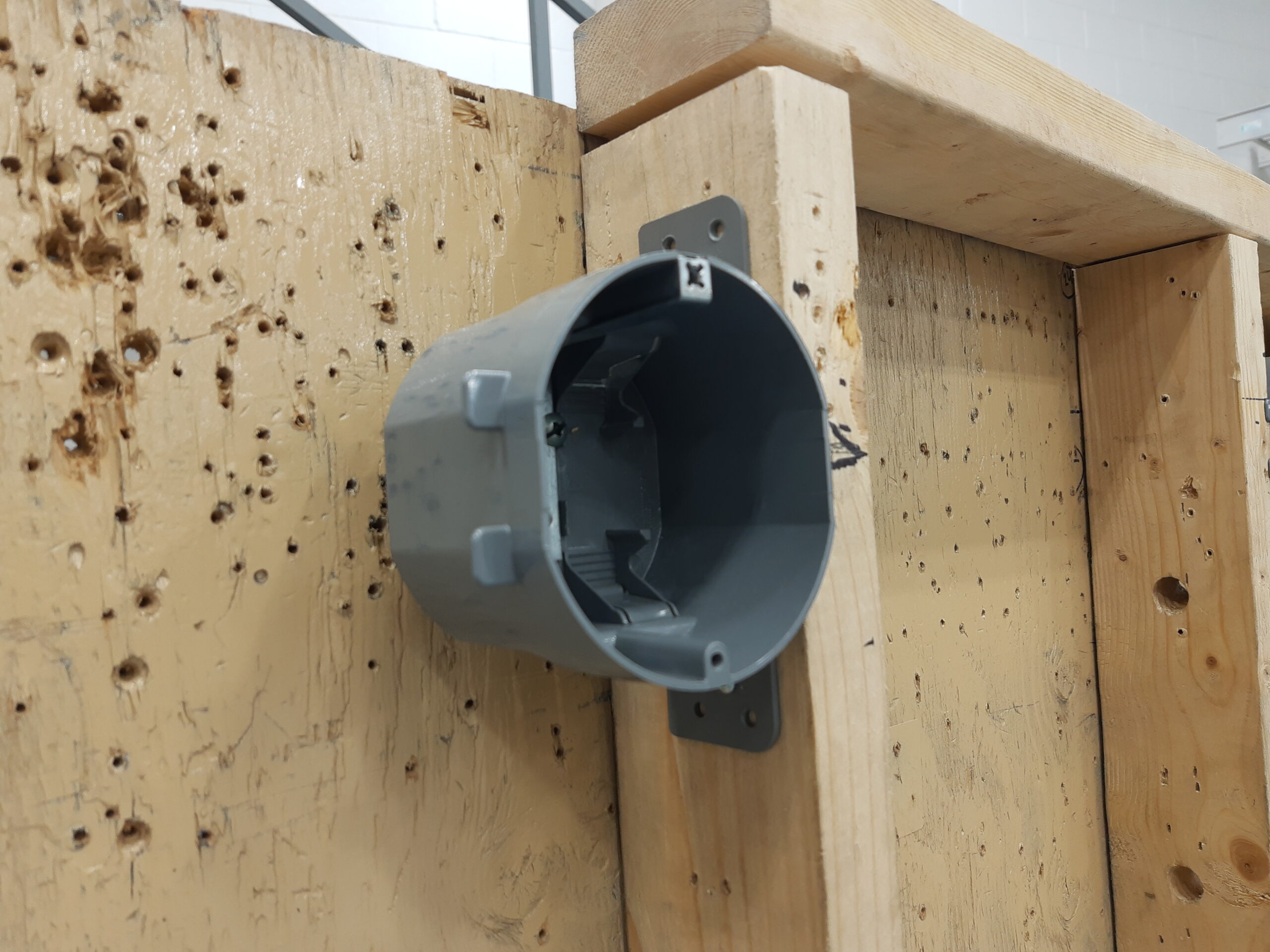 Start with the upper left octagon box: measure 6" down from the top of the upper 2x4, and make a mark on the leftmost stud. Line the octagon box to the LEFT of the 2x4 so the CENTRE of the box is at your mark and the plastic tabs are resting on the front of the stud.
 -
 Use your impact driver to insert two 8x1” wood screws (one for the top and one for the bottom) to secure the box to the side of the stud.
 -
Repeat with the second octagon box, attaching it at the same height to the left side of the far right stud as shown.
-
Measure 12” up from the bottom of the base 2x4 and make a mark on each of the three studs at this height.
-
Attach the boxes as shown, the far left one on the right side of the stud, and the middle and right boxes to the left of the studs. These will become three outlets.
-
Adjust the height of the three boxes so the BOTTOM of each box meets the 12” mark and the tabs are resting on the front of the studs. Use your impact driver and wood screws to insert screws into the top and bottom holes to secure the boxes.
-
Install the fourth single gang box for your switch: make a mark on the righthand stud at a height of 30” up from the bottom of the 2x4 base. Place your box on the LEFT side of the stud, the bottom of the box at the line. Add two wood screws to secure in place.
-
 Pull about 30’ (or five big hand-to-hand armlengths) of 14/2 wire from the spool, and cut it with your Linesman pliers, side cutters, or wire strippers.
 -
You will be “running”, “entering”, and “grounding” five lengths of wire to connect the 6 boxes as shown in the diagram and described in the next steps.
-
 Run the first wire: leave a 1’ end poking away from the left octagon box, run the wire through the hole in the stud and down to the leftmost single gang box. Leave 1’ of wire poking out from the lower box and cut the wire length with your side cutters or Linesman’s pliers.
 -
 Your 14/2 wire ends will all get pushed through the holes in the edges of the octagon and single gang boxes. As you see in the picture, you will strip the white jacket from the 14/2 to expose the three wires inside, leaving about 1” of white jacket remaining on the wires as they enter the boxes. This ensures that no internal wires are visible outside the boxes. Note: it is MUCH EASIER to remove the white jacket BEFORE you enter the wires.
 -
 Estimate the distance up the wire where you want to start removing the jacket, about 13” or 14” from the end. Use your utility knife to stab through the white plastic jacket (between the wires and back out the other side), then pull downward to split the white jacket.
 -
 Peel the jacket back and clip it away. You will see three wires exposed: a bare copper wire (this is the GROUND wire), a white insulated wire (this is the NEUTRAL wire), and a black insulated wire (this is the HOTWIRE).
 -
Push these three wires through the lower hole of your left octagon box until you have pushed about 1” of the remaining white jacket through the hole as shown. Your wires should be poking out from inside the box.
-
 Take the copper ground wire and wrap it around one of the screw heads at the back of the box. Tighten the screw with your impact or screwdriver to secure the wire.
 -
 Repeat steps 14 to 17 to enter and ground the other end of the wire down into the lefthand single gang box below.
 -
 Repeat steps 12-18 to run wire lengths between the left single gang box to the centre single gang box, as shown in red. Run the wires up above the boxes by about 8" as shown. Note: you only need to ground each box once, and it doesn’t matter which of the two copper wires you use.
 -
 Repeat steps 12-18 to run a wire up from the centre single gang box, through the hole in the centre stud, and down to the righthand single gang box as shown in red. Keep the wires tidy and uncrossed: enter the wires in the holes closest to the neighbouring boxes.
 -
 Repeat steps 12-18 to run a wire from the righthand single gang box up through the bottom of the upper single gang box (the switch), as shown in red.
 -
 Repeat steps 12-18 to run a wire out the top of the switch box to the octagon box above, as shown in red.
 -
 The wires should be supported or secured within 1’ of each box. If the wire runs through a hole in the stud, this is considered “supported”. You can also secure wire with staples.
 -
 To secure a single length of 14/2 wire, use your hammer to pound a small S1 staple over the wire and into the stud.
 -
 To secure two lengths of 14/2 at once, use a bigger S2 staple.
 -
Check your work: both upper octagon boxes should have the copper wire ground to the back of the box, and a copper, white, and black wire sticking out by about 1’.
-
 All three of your lower single gang boxes should have ONE copper wire ground to the back of the box, then two copper, two white, and two black wires hanging out by 1’.
 -
For each of the three outlet boxes, you will need to “pigtail” wires. This will mean making a “Y” shape: splicing three similar-coloured wire ends together – the two from the box with one piece of scrap wire. You need to do this because you can only connect ONE wire to the outlet fitting, and at the moment, you have two wires of each colour hanging out of each box.
-
First, pull all the wires forward and line them up in pairs: two bare copper grounds, two white neutrals, and two black hotwires.
-
 Pigtail the white neutral wires: use your Linesman’s to cut both white wires about 6” away from the box. Save one of the offcuts, and recycle the other. Use the 14 hole on the wire strippers to strip 1” of insulation from the ends of the three remaining wires as shown. Line the three wire ends up together.
 -
Hold the three wires with your non-dominant hand about 2” away from the ends. With your dominant hand, pinch the wires with your Linesman’s as shown, and turn them CLOCKWISE to make a tight, tidy twist in the wires. This may take some practice, don’t expect a perfect twist the first time!
-
Clip the end of the twist so the wires are all the same length.
-
 Twist a wire connector (eg, yellow Marette) onto the end of the twisted wires. Give it a sharp tug to make sure it doesn’t pop off. Inspect your wire connector: you should NOT see any bare wire exposed. If you do, remove the wire connector, clip the wire ends shorter, and replace the wire connector.
 -
 Repeat steps 30-33 for the black hotwires and bare copper grounds.
 -
 Tuck all the wires and connectors into the box so that three pigtailed ends are sticking out: one copper ground, one white neutral, and one black hotwire.
 -
Repeat steps 29 to 35 for each of the three single gang outlet boxes at the bottom of your frame.
-
 Look at the outlets: you will see three different screws on the sides: green, silver, and brass-coloured. The green is for GROUND, the silver are for NEUTRAL, and the brass are for HOTWIRES.
 -
 Choose one of the three single gang outlet boxes. Strip the last 1” of insulation off the white and black wires. Hook the ends of each wire: poke the stripped end through the hole in the side of the wire strippers. Twist your hand to make a 180° hook.
 -
 Hook the bare copper wire end over the GREEN-coloured screw on the side of the outlet. Tighten the screw to secure.
 -
 Hook the white neutral wire end over one of the SILVER-coloured screw on the side of the outlet. Tighten the screw to secure.
 -
 Hook the black hotwire end of over one of the BRASS-coloured screw on the side of the outlet. Tighten the screw to secure.
 -
 Stuff all the wires into the box, and arrange your outlet upright, lining up the outlet’s top and bottom holes with the holes on the box. Screw an 8-32 screw into each to secure the outlets in place.
 -
Strip 1” of the ends of the two white wires in the switch box on the righthand stud. Twist them together with the Linesman pliers, clip the ends to make them even, and twist a wire connector on.
-
Twist the two ground wire ends together, trim the end, and add a wire connector.
-
 Strip the last 1” of insulation off the two black wires and hook the ends. Hook them over the two brass-coloured wires on the side of the switch and tighten to secure.
 -
 Place the switch in the box with the wires to the RIGHT, this will ensure your switch is on in the up position.
 -
 Insert 8-32 screws on the top and bottom to secure the switch to the box.
 -
Make sure your copper wire is grounded (wrapped around the screw at the back of the box and tightened down with the impact).
-
Strip the last 1” of the black and white wires, and hook the ends.
-
 Hook the white wire to the silver screw on the back of the round lampholder, then tighten the screw to secure.
 -
Hook the black wire to the brass screw on the lampholder and tighten to secure.
-
Stuff the wires into the box, then insert and tighten two 8-32 screws (one top and one bottom) to secure the lampholder to the box. Be careful not to crack the plastic by over-tightening.
-
Screw a lightbulb into the lampholder.
-
Look over your work: make sure each wire is secured within 1’ of each box with an S1 or S2 staple. Wiggle each box to make sure the fittings are secure. Double check that your switch is DOWN and correctly oriented so that this is the OFF position.
-
 Get an electrician to wire in a male plug on a length of wire to your lefthand octagon box, and check your connections with a multimeter. Use a GFCI for extra safety.
 -
After the electrician has had a look at your work and safely plugs in your circuit to an extension cord, WITH THEIR PERMISSION, switch your light on to see if the light bulb lights up.
-
After you have tested your wall and taken some pictures of your hard work, demolish your wall.
-
Use your sidecutters to clip each wire right at the box entrances. Grip each staple and use your sidecutters like a hammer claw to pry them out.
-
Place your wires in one recycling bin, and the staples in another.
-
Unscrew all fittings carefully, removing the outlets, switch, and lampholder, and removing all the wire ends.
-
Twist off wire connectors and save, if possible.
Make the sample wall
Mount the octagon boxes
Mount the single gang boxes
Run and enter wires
Ground the box
Support the wires
"Pigtail" the wires
Install the outlet fixtures
Install the switch
Install the light
Final inspection
"Demo" your wall
Extension Challenges
- Add faceplates to the outlets and switch boxes.
- Ask an electrician to help you design and wire up a 3-way switch.
- Look at a sample wiring diagram for a residential building and see if you can figure out which symbols represent outlets, switches, lights, etc. Use what you learned and copy the style of the diagram to draw a representation of the circuit you wired up in this project.
- Visit a house in construction after the electrician has finished and before the walls have been installed. Do you see some of the techniques and fittings you used to build your sample circuit? Do you see any wiring configurations that you haven’t tried yet?